Peter McGovern D17124525 DT009 year 3 D.I.T
Abstract:
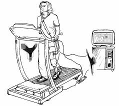
My project was to design and build a user friendly treadmill that could be used by a diverse range of people of varying fitness levels and ages.I have been a regular user of gym equipment and found that treadmills could be made much more interactive with the user by monitoring the users heart rate after the user had entered their vital statistics into the machine.
By monitoring the users heart rate the treadmill could be adjusted to suit their vital statistics and desired treadmill session goals.What this would entail would be if their heart rate got excessively high for their fitness level the speed of the treadmill would automatically slow down or gradually stop.This in my opinion would be a great advantage to people in avoiding injuries and not placing their heart under excessive stress.
I envisioned that the best users of this treadmill would be people recovering from medical issues or ongoing medical problems.
Example a middle aged man recovering from a heart attack.This man under medical supervision would be advised to take up regular exercise to strengthen his heart muscle but only under strict supervision.The man would use the treadmill in a supervised environment and the treadmill would be calibrated to give him a safe controlled work out.His heart rate would be constantly monitored and the readings collected to aid his recovery prevent injury and also give him a future of enhanced fitness levels.
To achieve my goal of an interactive treadmill i decided to build a miniature version of a treadmill and test it out in simulated conditions.
Design and Build:
As my project was going to be a miniature i needed it to be both portable but also of a size that could be easily observed and tested.The dimensions i chose were 34 cm long by 10 cm wide by 15 cm high.With the addition of the motor placed at the side the width would be 15 cm wide.
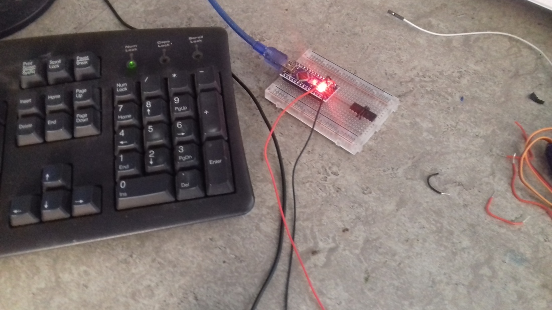
Components Used:
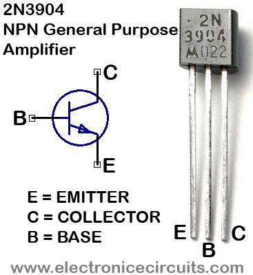
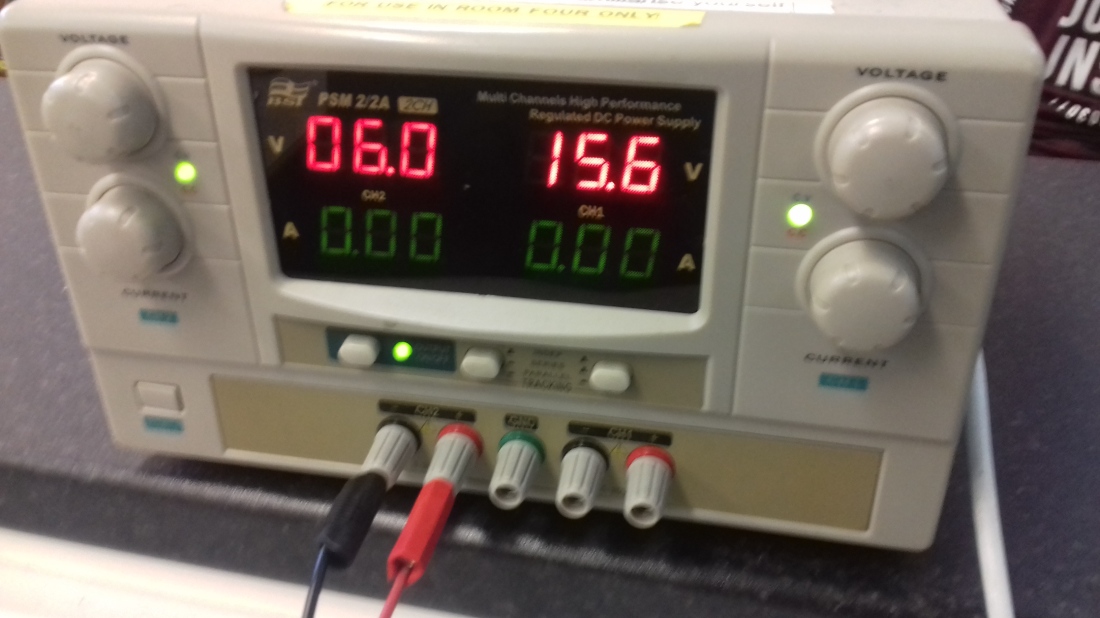
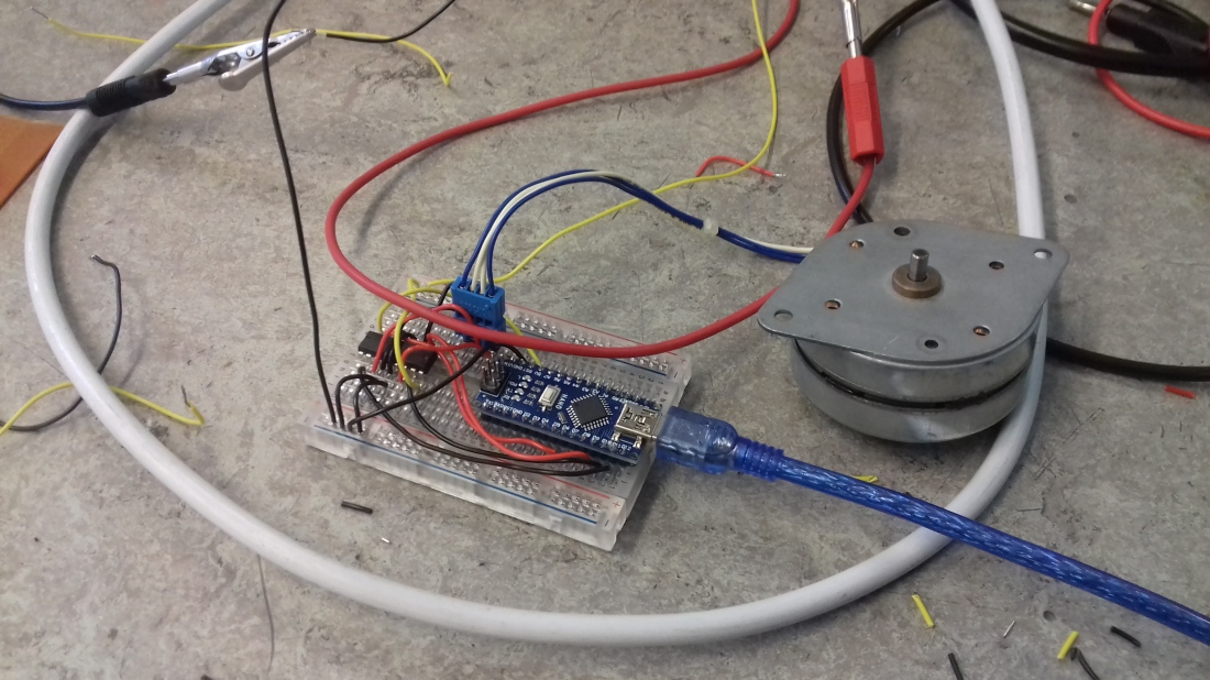
Arduino Nano, Breadboard, 5 Volt DC Motor, Driver Chip SN 754410, 3 Green LED lights, 3 breadboard switches, Colour sensor TCRT5000, Capacitor 220uF 35v, 3 resistors 10000 Ω, 3 Resistors 1000 Ω, Connectors, Cables 0.75 mm,
Treadmill Components:
Plastic 5mm, Cardboard 5mm, Round pipe pvc 20 mm, Rubber tube 6 cm width, 2 Metal bars round 4 mm,
Build:
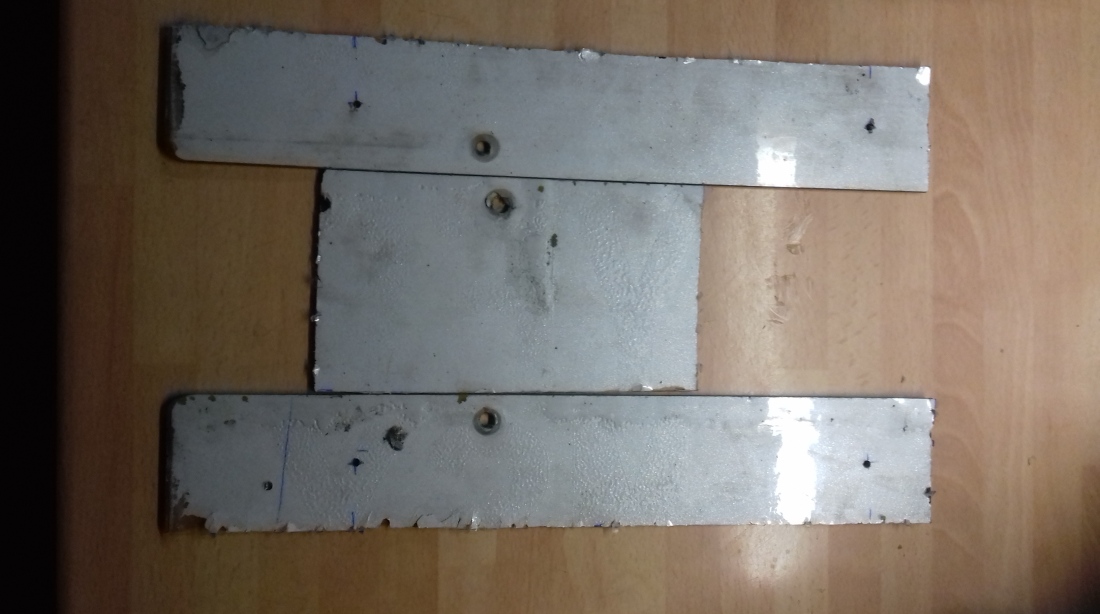
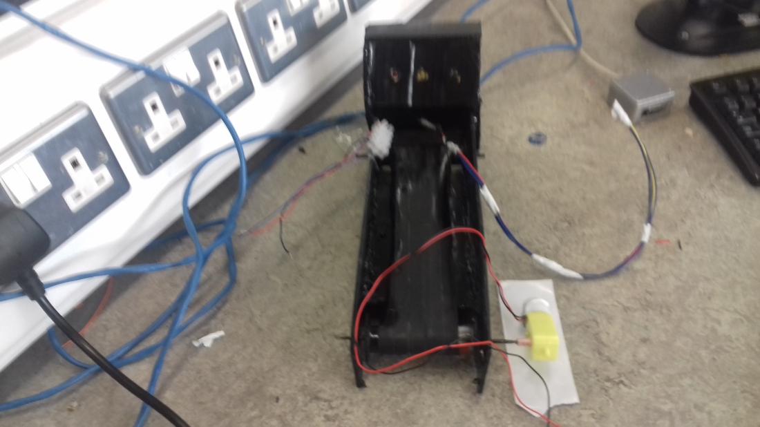
I decided that i wanted my treadmill to be lightweight but sturdy and i chose plastic for the frame as opposed to cardboard as i did not believe this to be rigid enough for multiple testings.I proceeded to cut out some plastic sheets into my required dimensions.
Plastic Frame
Next i cut up plastic pvc pipe 20 mm to use to rotate my treadmill belt.
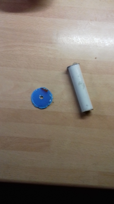
Finally i glued these components together.

Next was to build a control panel out of cardboard containing the 3 Led lights and 3 switches.
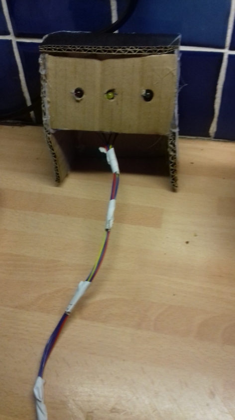
3 Switches
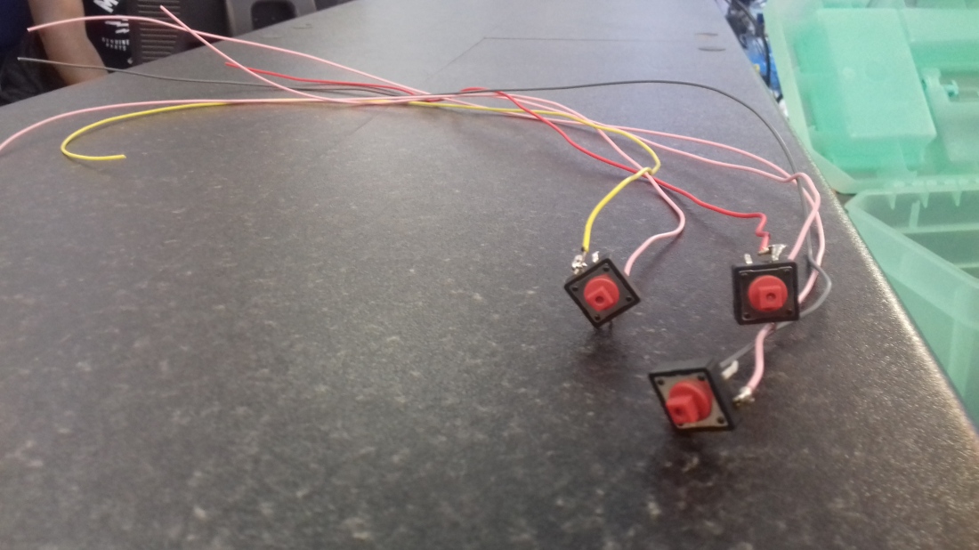
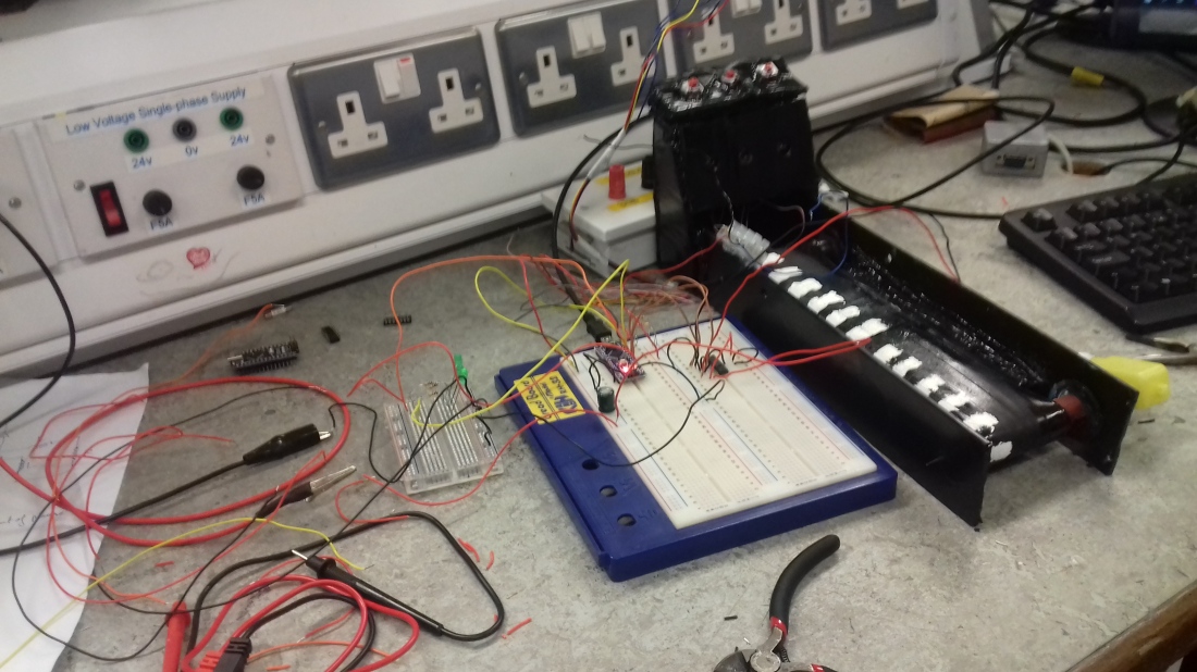
Built Treadmill
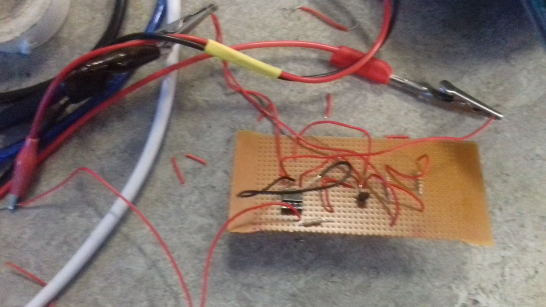
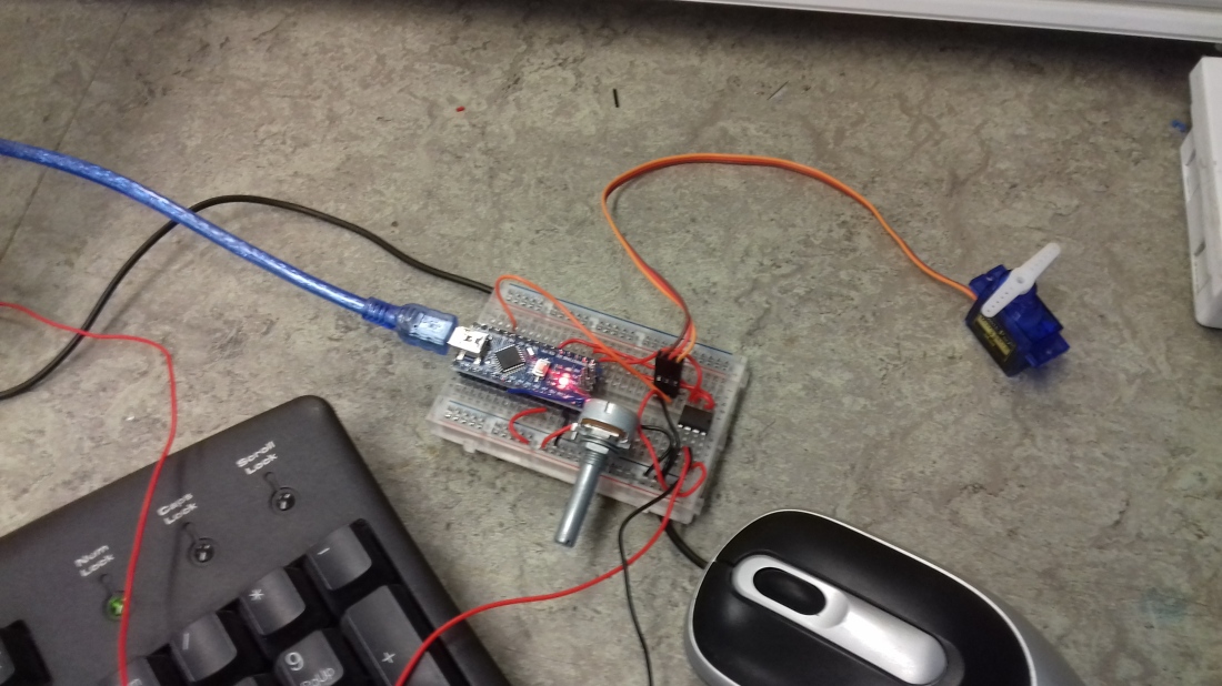
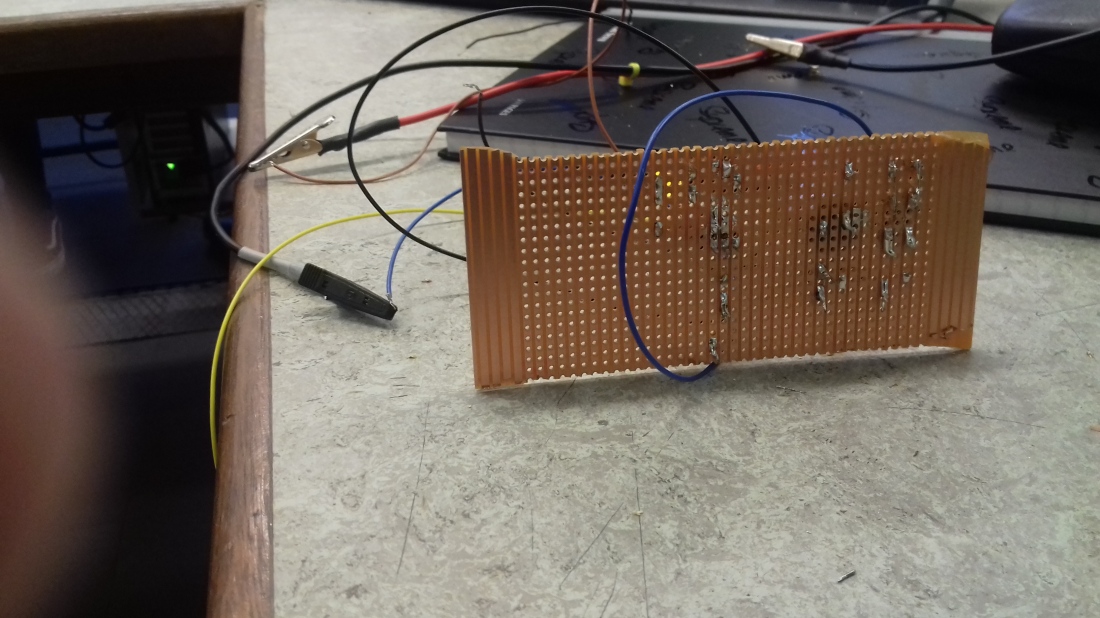
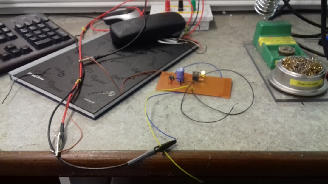
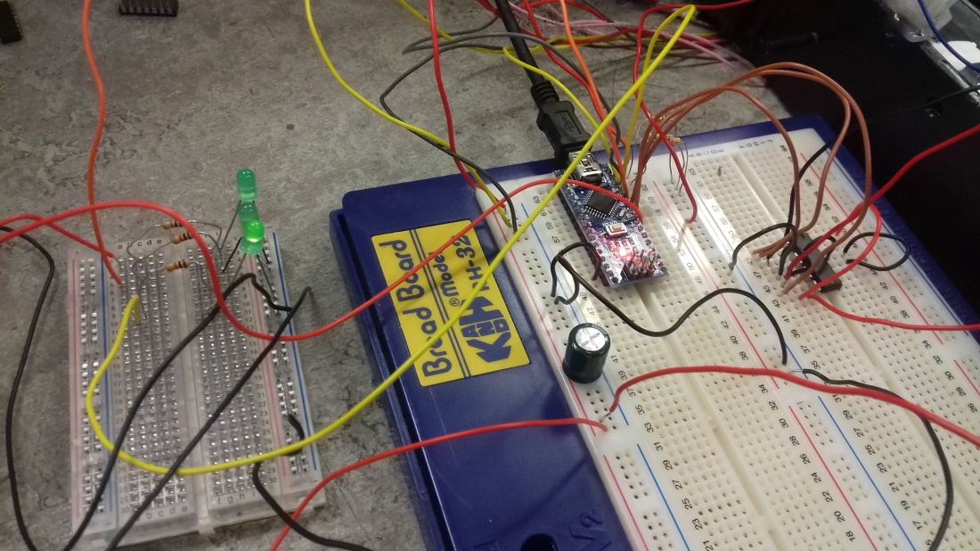
Breadboard Components inserted
Operation of Treadmill:
State Machine
State Description Actuators State Transitions 1 Red switch on Set motor speed off Colour sensor
2 Yellow switch on Set motor speed slow Colour sensor
3 Green switch on Set motor speed full Colour sensor
This was my initial procedure for my Treadmills operating principle but unfortunately i could not proceed with this plan so i altered my procedure.
Altered Operating Procedure:
State Description Actuators State Transitions 1 Red switch on Stop motor Green led on
2 Yellow switch on Slow motor Green led on
3 Green switch on Full speed motor Green led on
The new procedure would control the treadmill speed by means of the switches only,and each time a different switch was switched a different LED would illuminate.
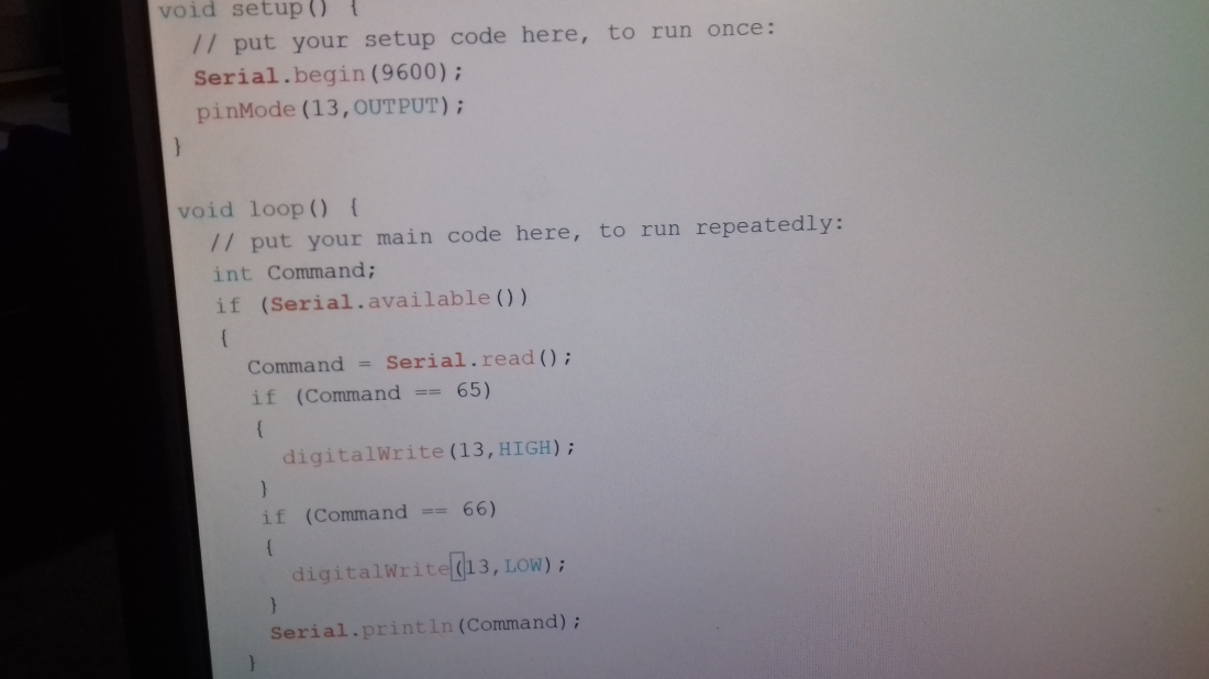
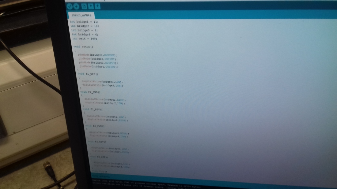
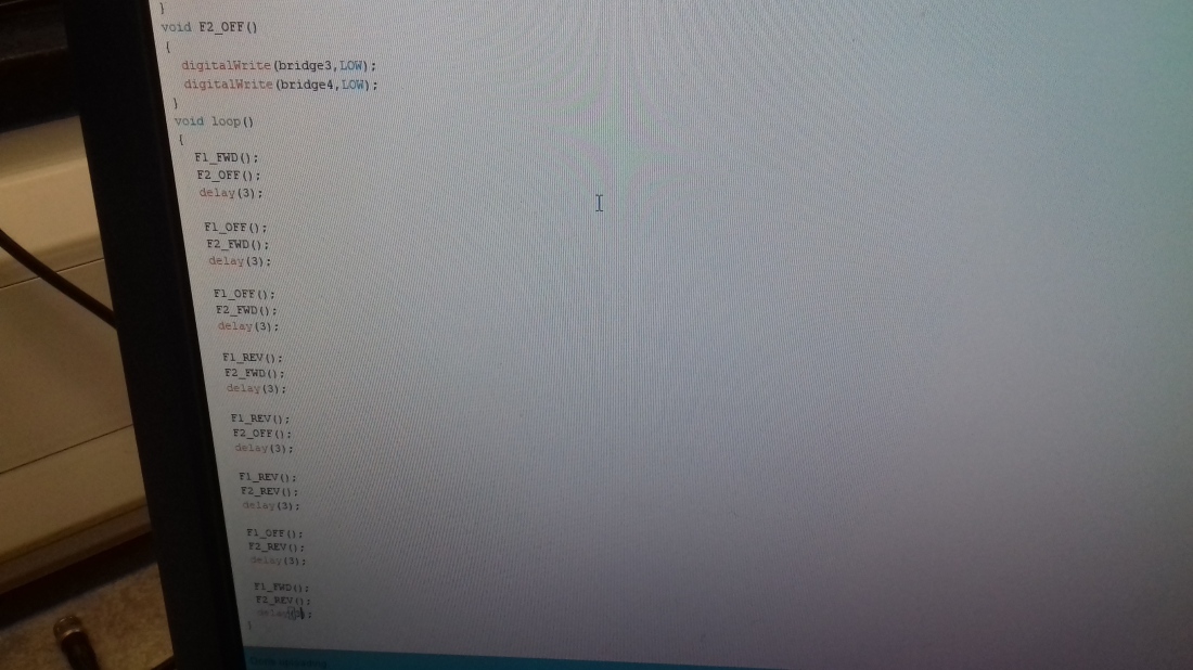
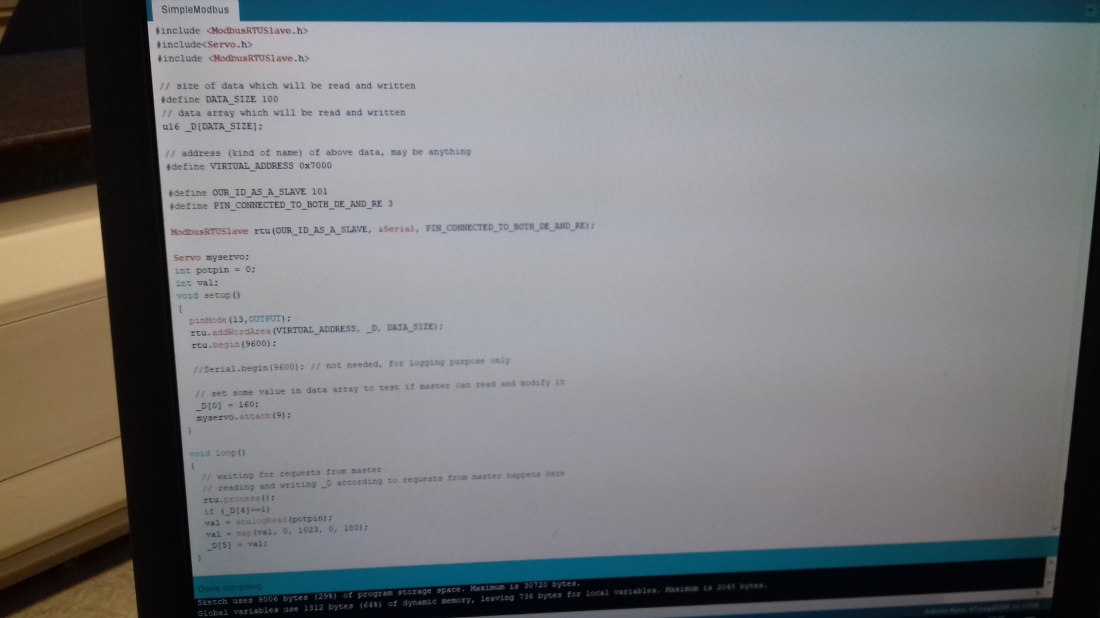
Arduino Nano Code
// // Peter McGovern Interactive Treadmill // Last updated 18/12/2018 //
int stopButton = 12; // stop int slowButton = 11; // slow int fastButton = 10; // fast
int redLed =9; // stop int yellowLed = 8; // slow int greenLed = 4; // fast
int motorSpeedPin = 5; int motorForwardPin = 6; int motorReversePin = 7;
int state = 1;
// The setup routine runs once when the power is switched on.////////////////////////////////////////////
void setup () .
{
// Digital outputs for LED
pinmode (redLED, output) ; pinmode (yellowLED, output) ; pinmode (greenLED, output) ;
// Digital outputs for motor
pinmode (motorSpeedPin, output) ; pinMode (motorForwardPin, output) ; pinMode (motorReversePin, output) ;
// Digital inputs for buttons
pinMode (stopButton, input) ; pinMode (slowButton, input) ; pinMode (fastButton, input) ;
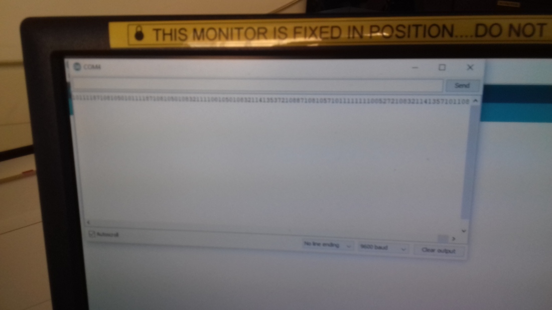
// Open serial port to display colour readings on screen serial .begin (9600) ;
}
// Simple version void loop () { if (state == 1) // STOP { // Actuators digitalWrite (motorForwardPin, LOW) ; digitalWrite (motorReversePin, LOW) ; digitalWrite (redLED, HIGH) ; digitalWrite (yellowLED, LOW) ; digitalWrite (greenLED, LOW) ;
// Change state ? if (digitalRead (slowButton) == 1) state = 2 ; if (digitalRead (fastButton) == 1) state = 3 ; } else if (state == 2) // SLOW FORWARD { // Actuators digitalWrite (motorForwardPin, HIGH) ; digitalWrite (motorReversePin, LOW) ; analogWrite (motorSpeedPin, 255) ; digitalWrite (redLED, LOW) ; digitalWrite (yellowLED, HIGH) ; digitalWrite (greenLED, LOW) ;
// Change state ? if (digitalRead (stopButton) == 1) state = 1 ; if (digitalRead (fastButton) == 1) state = 3 ;
} else if (state == 3) // FAST FORWARD { // Actuators digitalWrite (motorForwardPin, HIGH) ; digitalWrite (motorReversePin, LOW) ; analogWrite (motorspeedPin, 255) ; digitalWrite (redLED, LOW) ; digitalWrite (yellowLED, LOW) ; digitalWrite (greenLED, HIGH) ;
// Change state ? if (digitalRead (stopButton) == 1) state = 1 ; if (digitalRead (slowButton) == 1) state = 2 ; } else if (state == 10) { while (1) { // forward fast digitalWrite (motorForwardPin, HIGH) ; digitalWrite (motorReversePin, LOW) ; analogWrite (motorSpeedPin, 255) ; digitalWrite (redLED, LOW) ; digitalWrite (yellowLED, LOW) ; digitalWrite (greenLED, HIGH) ; delay (2000) ;
// reverse slow digitalWrite (motorForwardPin, LOW) . digitalWrite (motorReversePin, HIGH) : analogWrite (motorSpeedPin, 100) ; digitalWrite (redLED, LOW) ; digitalWrite (yellowLED, HIGH) ; digitalWrite (greenLED, LOW) ; delay (2000) ;
// stop digitalWrite (motorForwardPin, LOW) . digitalWrite (motorReversePin, LOW) . analogWrite (motorSpeedPin, 255) ; digitalWrite (redLED, HIGH) ; digitalWrite (yellowLED, LOW) ; digitalWrite (greenLED, LOW) ; delay (2000) ; } } }
Testing
Testing: To test my treadmill i alternated between the different switches and it performed well to the arduino code.My yellow LED and Green LED stopped working after a few tests were conducted so i placed 3 green LED’s to the left of my treadmill to show the different stages of the treadmill in operation.Treadmill performs very well.
The first button red LED stops the treadmill
The second button yellow LED makes the treadmill run slow.
The third button green LED makes the treadmill run at full speed.
To watch my Treadmill in Operation please go to this address
Video https://youtu.be/aKs171lDa00